I obtained a 1974 Porsche 914 from which the engine had already been removed, which simplified the preparation somewhat (though missing parts also complicated it). As a mid-engine car, it was well suited to carrying battery without throwing off the weight balance. The conversion process involved:
- Rust management and painting
- Restoration (new brakes, rebuilt axles, etc)
- Mating the electric motor to the transmission (using pre-made parts from ElectroAuto)
- Designing, building, and installing battery racks/boxes
- Designing the battery management system
- Mounting and wiring the electrical system
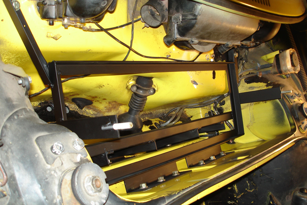
First, I stripped out everything leftover from the old internal combustion engine, including the gas tank, several hoses, sound barrier, etc. The floors in the cabin and the trunk got stripped, patched, and painted with rust-preventative POR-15, as did the bumpers and rusty spots in the engine compartment. After welding in the support structure for the battery racks, I gave the engine compartment a full coat of paint.
Motor Adapter
The car is propelled by a 9″ diameter, series wound DC motor weighing approximately 160lbs. A taperlock hub is installed on the shaft to provide a 5-bolt pattern to which the original flywheel attaches. A bracket on the rear of the motor allows it to bolt to the crossbar which originally supported the engine.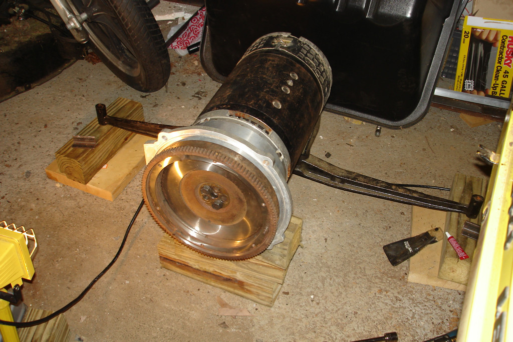
An aluminum spacer and adapter plate enable the motor to be bolted to the original 5-speed manual transmission:
Mounting the hub to the shaft proved especially tricky. Multiple attempts and even the first several thousand miles of driving suffered from vibration problems due to flywheel imbalance. I had the flywheel and pressure plate assembly precision balanced, but the issues persisted. Eventually, through careful measurement, I was able to identify an axial runout in the motor hub. I was able to correct it reasonably well, though not perfectly. First, I used a shim to correct the runout on the face of the adapter; this ensured the flywheel only experienced radial run-out. I was then able to correct the center of gravity by adding extra washers to the flywheel bolts.
Battery Boxes
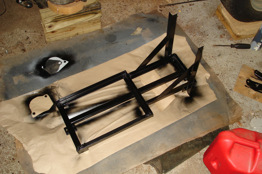
I fabricated the battery racks from 1″ angle iron and square tubing (1/8″ thick). Everything was cut with an angle grinder and a chop saw, then welded using a wire-feed welder (flux core). My original design was for 16 lead acid batteries (Optima Yellow Top or equivalent).
There is a front battery rack which occupies the space that previously housed the gas tank (directly in front of the windshield). This was designed to hold 4 batteries.
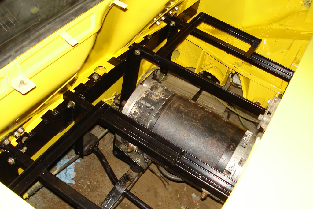
The remaining 12 batteries were designed to mount in the engine compartment, directly behind the seats. The rack has 2 layers, with the lower batteries straddling the motor. Top rack shown here (also, motor):
The front of the rack rests on and is bolted to the flange in the front of the compartment.. Additionally, the top racks bolt through the front firewall to provide rigidity and strength. The rear of the rack is supported by a 1″ square tube spanning the width of the engine compartment. This is supported on either end by a larger square tube which is welded to the chassis, just behind the suspension mount.
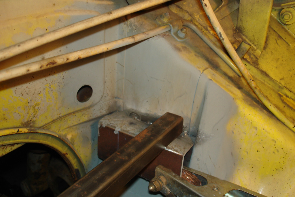
The lower racks bolt in and are suspended from the top rack:
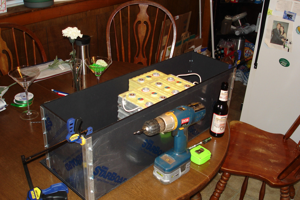
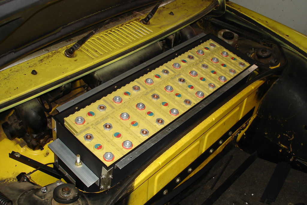
As time marched on, Lithium Iron Phosphate batteries became a viable and affordable option. Instead of a 10kWh, 700lb, $3200 battery with life of 300-500 cycles (to 50%), I was able to install a 17kWh, 400lb, $7500 battery with life of 1000 cycles (to 80%) and deeper discharge capability. The steel racks were already fabricated for the lead batteries, so I created boxes out of marine grade polymer to hold the lithium batteries – 54 cells in total.
Assembling a battery box in the kitchen of our 500 sq ft Somerville apartment, where it shared the kitchen table with prototype wedding favors/centerpieces:
The front box was designed to accommodate 16 cells:
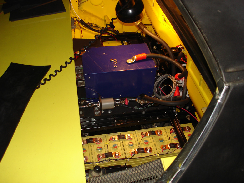
The lower rear racks each hold 9 cells. This purple box is the original motor controller, a DC Power Systems T-Rex (1000 Amp/400V), which is mounted on a polymer plate above the motor. The T-Rex used an inductive throttle sensor (also shown); it is actuated by the car’s original throttle cable.
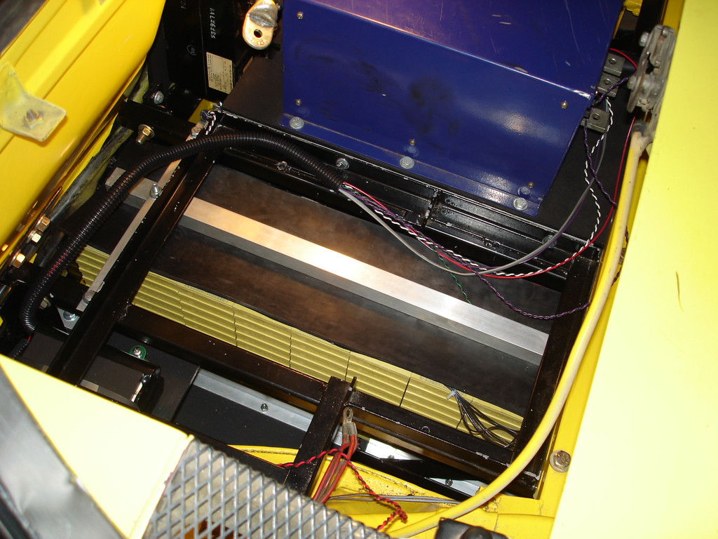
The bottom battery connections are insulated by a sheet of neoprene and held in place by an aluminum bar which runs down the center.
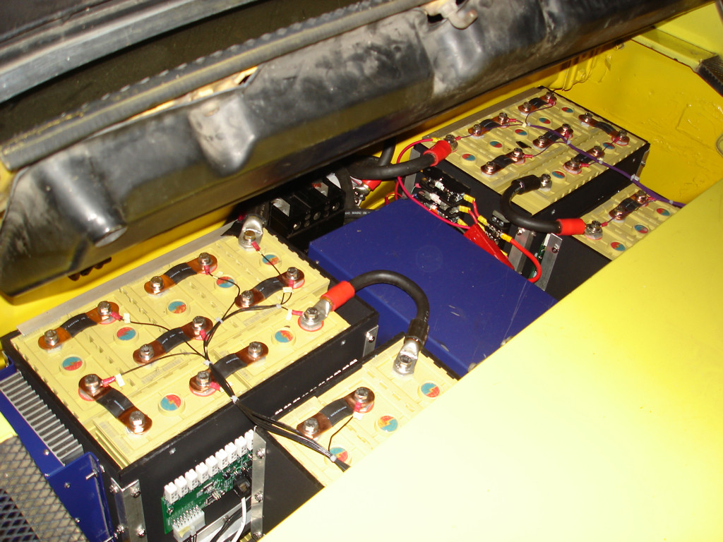
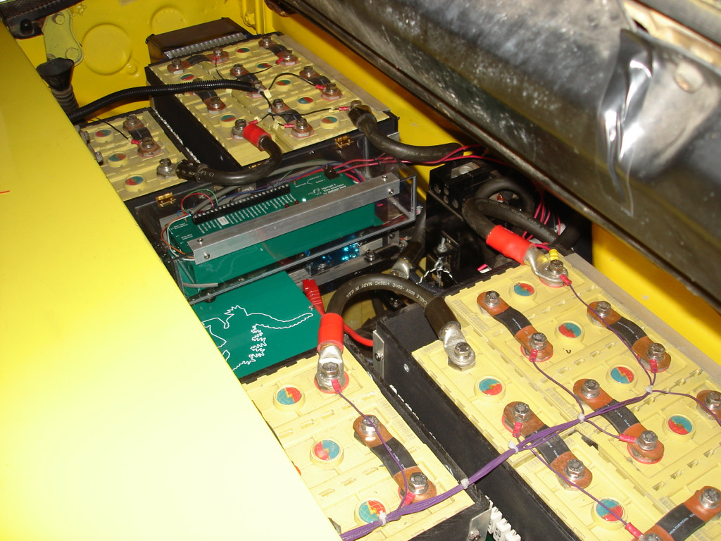
To accommodate the geometry of the top rack, a total of 4 boxes hold the remaining 20 batteries. In addition to the top battery boxes, you can also see the DC/DC converter (purple, far left), which supplies power for the 12V system from the main traction pack, and one of my custom BMS modules.
Electrical System
The 54 lithium ion cells are wired in series to produce a 170VDC (nominal) battery. Within each battery box, the cells are tied together using copper straps from the batter supplier. Between boxes, I used 2/0 welding cable. I used 4/0 welding cable between the controller and the motor, which can regularly see currents as high as 1000A.
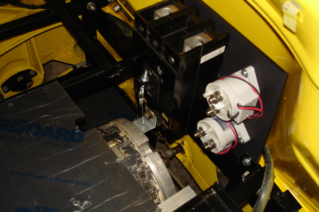
Both the positive and negative legs of the battery are disconnected from the motor controller when the car is powered off using Kilovac EV-200 contactors (giant relays); one is under key switch control, the other is closed by the motor controller after its internal capacitors have pre-charged through a resistor (to prevent arcing). Additionally, a 250VDC, 1000A circuit breaker acts as an emergency disconnect. All three are mounted to the firewall in front of the controller.
The switch on the breaker is actuated by the 914’s heater control lever using wire rope. The heater lever is the perfect emergency disconnect: a bright red handle with a satisfying action conveniently located behind the shift selector knob.
The original T-Rex motor controller was purchased used, vintage 2000, and suffered reliability issues from the beginning. Most troubling was a connector between the control PCB and the power stage which lost contact and stranded me on the side of the road multiple times. Sometimes literally punching the controller helped; others it had to be fully disassembled and the connector reseated. Just a few hundred miles after a rebuild that finally fixed the connector issues, the whole controller gave out in traffic, its IGBTs failing shorted. I replaced it with a Cafe Electric Zilla Z1K, which has been awesome.
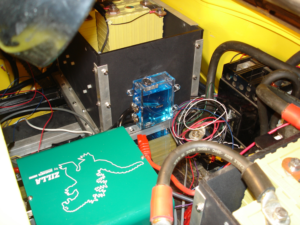
The controller is mounted to a clear lexan plate above the motor. It is liquid cooled with a heat exchanger and fans mounted under the rear trunk next to the transmission. The controller is shown with coolant reservoir below.
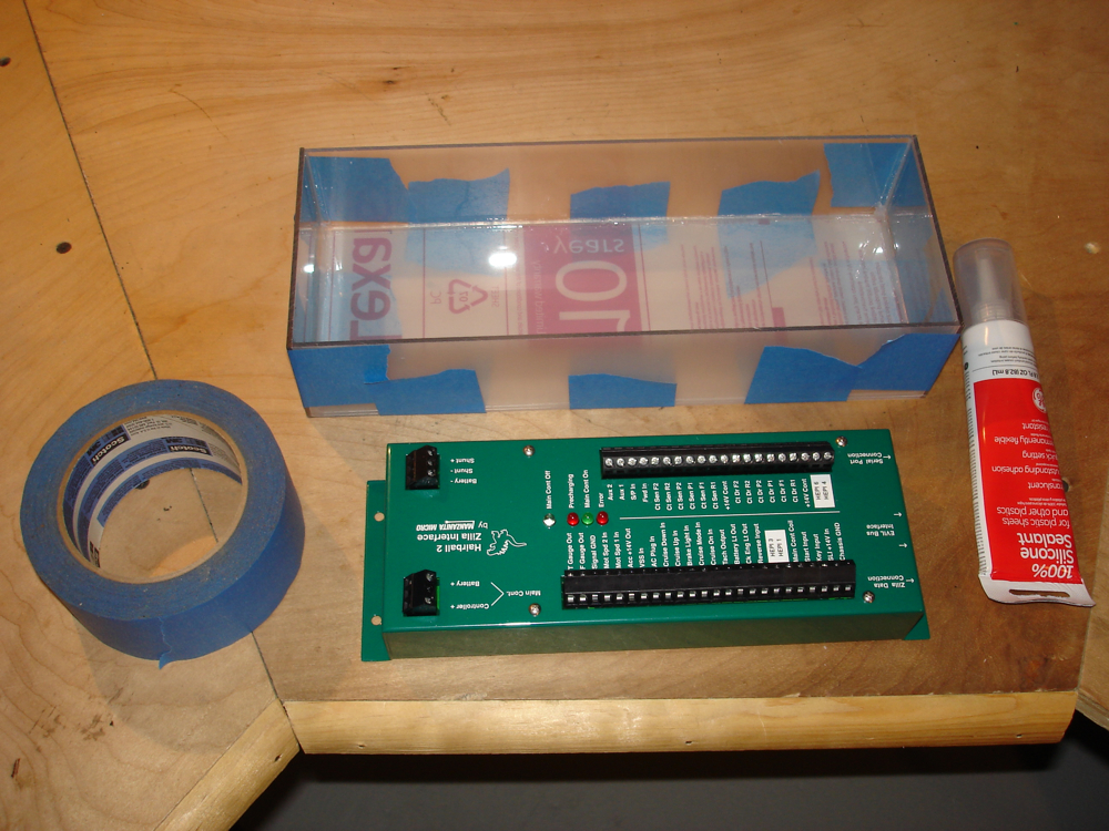
The Zilla has an external control module called the “hairball.” Since it’s less protected from the elements, I created a custom clear acrylic enclosure to mount it.
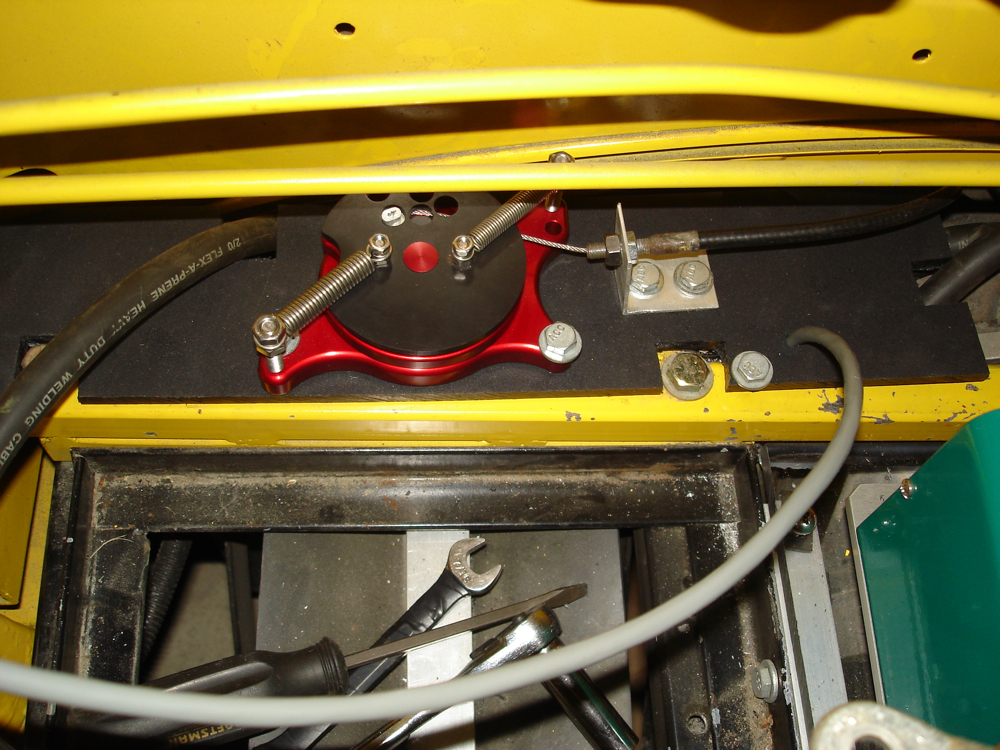
Instead of the inductive throttle, the Zilla typically uses a potentiometer or hall effect pedal. I was able to get it to work with throttle cable-actuated hall effect sensor from Netgain Controls, which is mounted behind the right top battery rack..
The full engine compartment is shown here (minus acrylic safety cover):
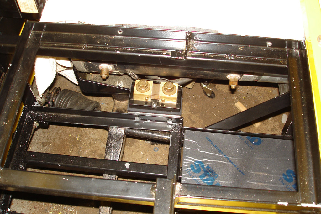
Motor current is sensed with a 1000A shunt located in the motor current loop.
The motor current gauge and controller status indicators live in a custom gauge that occupies the space previously used for the fuel gauge and alternator, oil, and brake warning lights.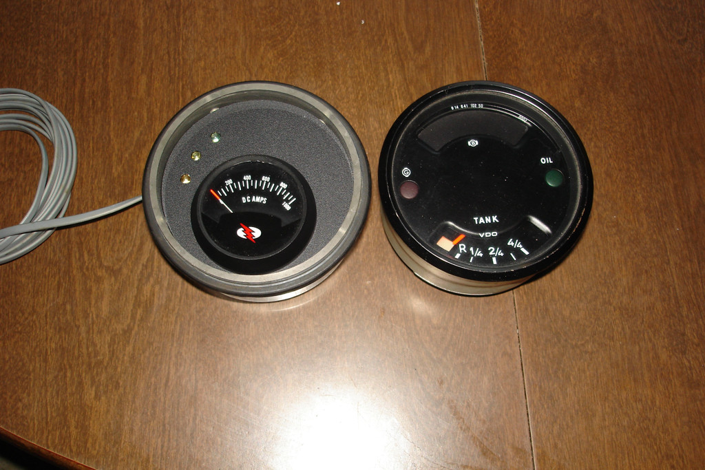
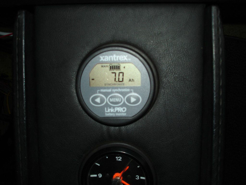
A Xantrex LinkPro battery monitor measures pack voltage and current and provides fuel gauging/state of charge measurement. It takes the place of the engine temperature gauge in the center instrument cluster.
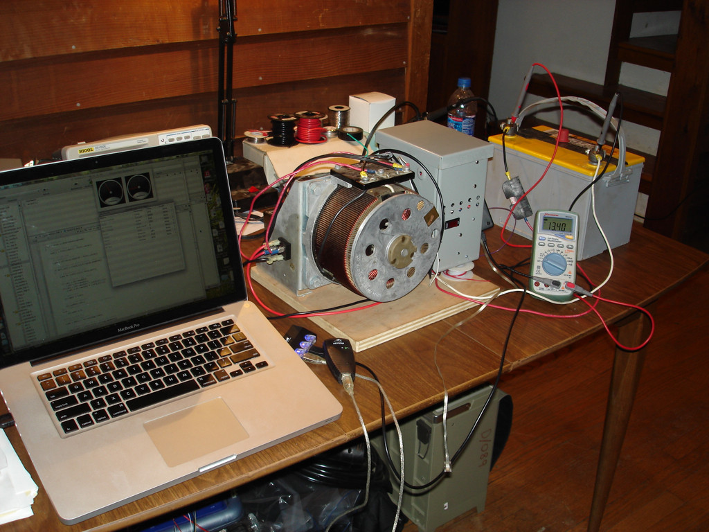
My original charger was a hacked-together solution using a motorized 20A variac, bridge rectifier, and active ripple cancellation. The variac was microprocessor controlled to produce a DC voltage roughly 12V higher than the battery. A microprocessor-controlled BJT current source provided pure DC charging current to the pack. The 12V headroom enabled the current source to fully cancel the 120Hz ripple in the filter capacitors. Max charge current was 5A. The unit is shown being bench-tested on a 12V battery.
After several thousand miles, the variac solution was eventually replaced with a 1500W power factor corrected and isolated charger from Elcon which currently resides in the front trunk. Mains power is detected by the BMS to begin charging. The BMS controls a relay between mains and the charger to enable it to interrupt charging in the event of a fault condition.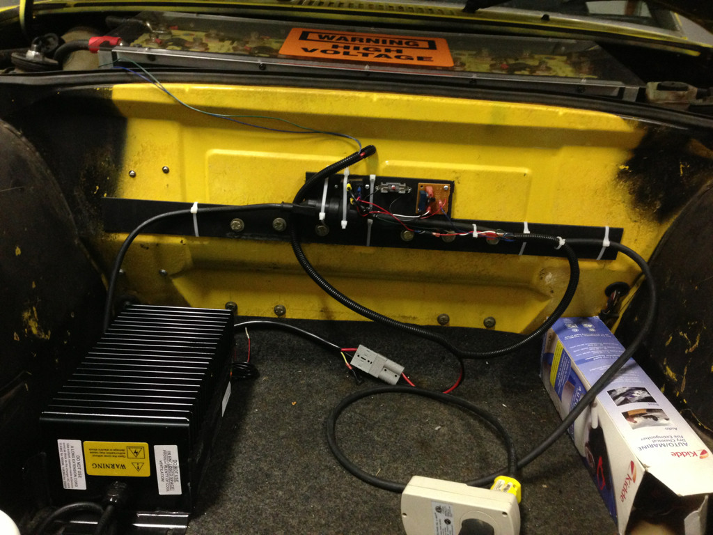
In all, and for many reasons, it was a nine year process and several hundred hours of labor from the day I bought the car to my first drive in it. It has been an ongoing project in the years since with upgrades to both the EV system and to the original car, including new suspension, a transmission rebuild, and more. For both the journey and the result, it was worth it.
Acknowledgements
I have deep gratitude for many people who helped make this conversion possible. These are only a few:
Seth Murray, my dear friend from college who introduced me to the world of electric vehicles and provided invaluable advice.
Fran Yates, who gave me garage space while I was still in college and needed a place to store and work on the car, and who was a great benefactor in many other ways.
Bill Brown, without whose garage space, tools, and advice the project would have likely been abandoned.
The EV List community, whose expertise and advice helped me overcome many challenges.
My wife, Sara, who offered great patience and support for my hobby.

